
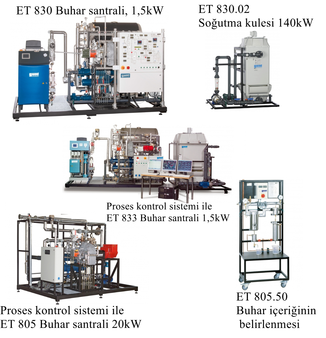
ET830
Steam power plants, thermal energy is first converted into mechanical energy and then into electrical energy. A steam power plant essentially consists of a heat source for generating steam, a turbine with load, and a cooling mechanism for condensing the steam.
ET830.02
The forced draught wet cooling tower is integrated into the cooling water circuit of the ET 830 steam power plant. It provides recooling for the condenser cooling water used in the steam power plant. Evaporation losses are automatically compensated for. Temperature, air humidity and water flow rate at the inlet and outlet of the cooling tower can be read directly on the device.
ET833
Nowadays large process engineering systems, such as steam power plants, are managed with process control systems (PCS). The entire system is monitored, actuators regulated and controlled, measurements recorded and displayed via the process control system.The steam power plant ET 833 is specifically designed for training purposes in the field of power plant engineering with process control systems. The system operates very similarly to real large-scale plants due to the high degree of complexity.
ET805
Nowadays large process engineering systems, such as steam power plants, are managed with process control systems. The ET 805 Steam Power Plant is specifically designed for training purposes in the field of power plant engineering with process control systems. Due to the size and complexity of the system, in many aspects the operating behaviour corresponds to that of actual large-scale plants, thereby enabling training that is as close to the real thing as possible. The plant consists of four separate modules and can therefore be flexibly adapted to the space available in the laboratory:
ET805.50
The vapour content x is a dimensionless ratio between 0 and 1. It is defined by the ratio of mass of vapour and total mass. The total mass is calculated from the sum of fluid mass and vapour mass. ET 805.50 uses water as working medium. Water vapour is also known as steam. The ET 805.50 trainer uses a two-stage method to determine the vapour content.
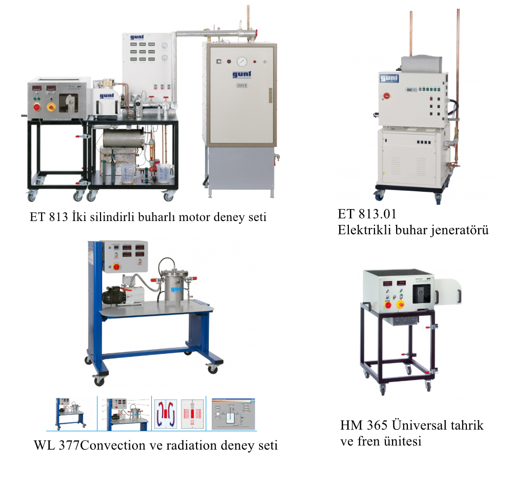
ET813
In a steam power plant, thermal energy is converted into mechanical energy, and ultimately into electrical energy. A steam power plant consists of a heat source for generating steam, a turbine or steam engine with generator, and a cooling device for condensing. The steam engine is used to convert thermal energy into mechanical energy.
ET813.01
The ET 813.01 electrically heated steam generator is intended to supply the ET 813 steam engine with saturated steam. The ET steam generator 813.01, in conjunction with the ET 813 steam engine and the HM 365 universal drive and brake unit, forms a complete steam power plant.
HM365
HM 365 is the base module of the GUNT-FEMLine, on which students can carry out experiments on fluid machinery. This equipment series covers five training courses on water and oil pumps, turbines, and systems engineering and engine technologies.
WL377
Under real conditions, the heat transport between two objects is normally substance-bound, i.e. convection and/or heat conduction, and not substance-bound, i.e. radiation, at the same time. Determining the individual heat quantities of one type of transfer is difficult.The WL 377 trainer enables users to match the individual heat quantities to the corresponding type of transfer.
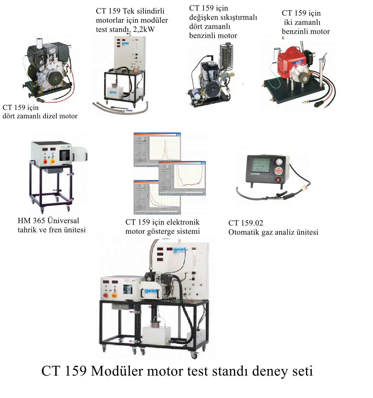
CT159
This test stand measures the power output of internal combustion engines delivering up to 2,2kW. The complete test stand consists of three main elements: The CT 159 for mounting of the engine and as a control unit, the universal drive and brake unit HM 365 as a load unit and a choice of engine: four-stroke diesel engine (CT 151), two-stroke petrol engine (CT 153) and two four-stroke petrol engines (CT 150 or CT 152 with variable compression).The main function of CT 159 is to mount the engine, supply it with fuel and air and record and display relevant measurement data. The engine is mounted on a vibration-insulated base plate and connected by way of a belt drive to HM 365.The measured values are transmitted directly to a PC via USB. The data acquisition software is included.
CT159.01
Indicating systems can be used for a thermodynamic analysis of engines. In industrial applications, these systems are used to optimise the combustion process.The system is used in conjunction with the transducer sets CT 159.03, CT 159.04 and the CT 159.05. Each of the sets consists of a pressure transducer and a TDC sensor. It allows pressure measurements to be carried out in the cylinder head of an internal combustion engine and is designed for the CT 150, CT 151, CT 152 and CT 153 engines. The data is transferred to a PC for further processing. The software produces p-t and p-V diagrams, and also displays the average pressure and the indicated power output.The system consists of software and a measuring amplifier for the pressure transducer and TDC sensor.
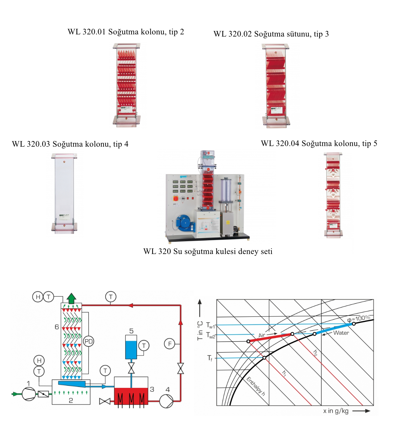
WL320
Wet cooling towers are a proven method of closed-circuit cooling and heat dissipation. Typical areas of application are: air conditioning, heavy industry and power plants.
WL320.02
Cooling columns contain wet deck surfaces. The cooling capacity of a cooling column is determined by the surface of these wet deck surfaces.WL 320.01 contains a small wet deck surface. The cooling column type 2 is placed into WL 320 instead of the column type 1. The cooling capacity of both columns is compared.
WL320.03
Cooling columns contain wet deck surfaces. The cooling capacity of a cooling column is determined by the surface of these wet deck surfaces.WL 320.02 contains a large wet deck surface. The cooling column type 3 is placed into WL 320 instead of the column type 1. The cooling capacity of both columns is compared.
WL320.04
WL 320.03 contains a cooling column without a wet deck surface. The cooling column type 4 is placed into WL 320 instead of the column type 1. The heat transfer in the free water drop can be studied using this cooling column.
WL320.05
Cooling columns contain wet deck surfaces. The cooling capacity of a cooling column is determined by the surface of these wet deck surfaces.WL 320.04 contains divided wet deck surfaces. The cooling column type 5 is placed into WL 320 instead of the column type 1. It is possible to variably arrange the wet deck surfaces. Additionally, plates are fitted into the cooling column. The cooling capacity of both columns is compared.